
The traditional saying goes “An image is worth a thousand words”, and I strongly believe this applies to diagrams as well. It doesn’t matter how many words we spend trying to explain the nuances of a system: sometimes we just need a simple diagram to put all the pieces together.
For many decades, there were different software diagram notations competing with each other. In the late 1990s, the authors of the three most popular methods worked together to develop a Unified Modeling Language, or UML for short, which is now the industry standards.
Having a universal language to describe software with diagrams is extremely powerful to convey intention and meaning in a clear and concise way. However, this only works if we know the language.
Since not everyone is familiar or comfortable with UML, I’ve prepared this article as a practical introductory guide to what are, in my opinion, the three essential UML diagrams every software engineer should be comfortable with.
Essential UML Diagrams
Class diagrams
Class diagrams are representations of the classes and interfaces of a system and how they relate to each other. I find them particularly useful for communicating changes to the classes in a system. Also, they can be used to document all class relationships, with a word of caution: we should only do this using tools that automatically generate those diagrams.
In UML, a class can be as simple as a rectangle with the class name, and an interface is the same, but with the text <<interface>> on top of it. We a class implements an interface (a.k.a. realization), we connect the class and the interface rectangles using a dashed arrow with a hollow head on the interface side:
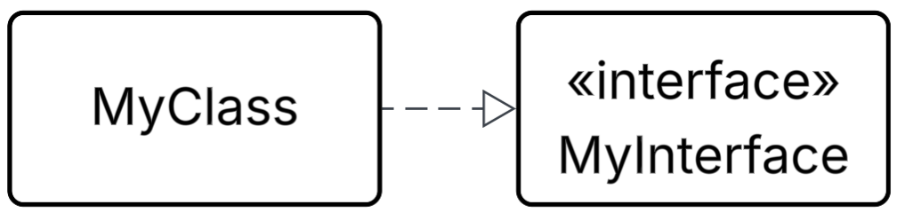
class MyClass implements MyInterface {}
Inheritance, or Generalisation, is represented as a solid arrow with a hollow head on the Base class:
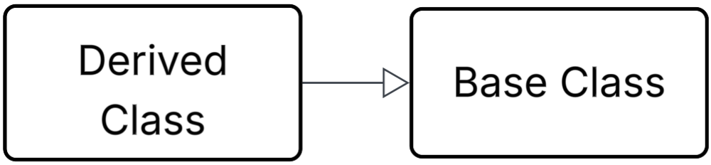
class DerivedClass extends BaseClass {}
We call association when a class uses or references another class or interface. This can be represented with a solid line without an arrow head.
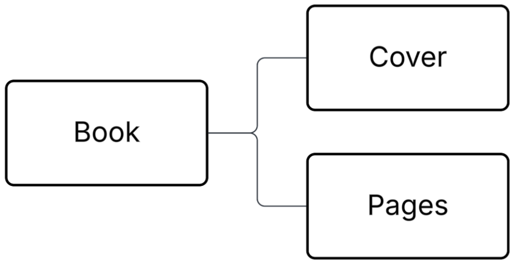
interface Cover {...}
class Pages {...}

class Book {
  constructor(cover: Cover) {
    this.pages = new Pages();
    this.cover = cover;
  }
}
UML also allows us to specify what are the attributes and methods of our classes or interfaces, or to be even more specific as to the nature of the relationships between classes, but the notations above are a good starting point, specially if you’ve never used a class diagram before.
Use case diagram
Use case diagrams are extremely helpful to identify the requirements of a system from a user’s perspective. The main idea is to show all the ways in which users are expected to use our system, or use cases, and what components or systems are involved in it.
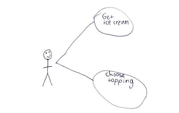
In fact, the protagonists of use case diagrams are our users. We represent them as stick persons, called Actors, while the use cases are represented using ellipses. At university, we would not get full marks if we drew Actors with happy faces 🙂 , and there’s some merit in that. If you want to stay professional, the standard notation is your best bet.
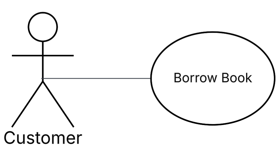
For example, we could start modelling a library system where the Customer of a Library wants to borrow a book:
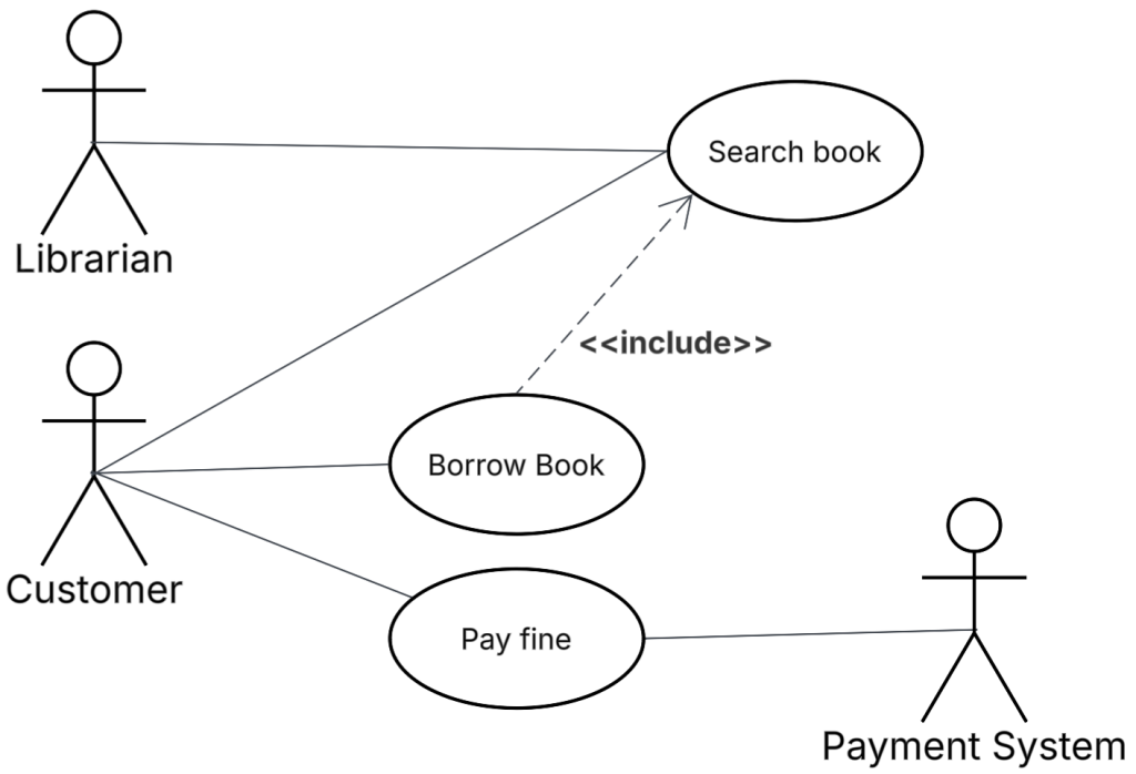
But that was too simple. Let’s extend the example so that Customers can pay fines through our system. For this, we’ll need to communicate with a Payment System actor. This means that Actors can be people or other systems.
Multiple actors can have the same use case, for example, Librarians and Customers must be able to search for books. And Customers can borrow books, which requires them to search for the book to borrow: this is represented with a dashed arrow with the word “<<include>>“.
As you can see, use case diagrams are designed to be simple and lightweight so everyone, even non-technical people, can easily see what our users are expected to do with our system.
I personally find the use case diagrams extremely useful as a mechanism to identify any requirements that may be missing while I plan projects, and also to set expectations with stakeholders on their scope.
Sequence diagram
Sequence diagrams are used to describe the order in which data is transferred between entities. An entity can be anything that sends or receives data, a class, a microservice, an API, a data broker, etc.
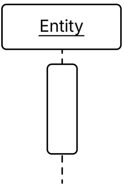
An entity is drawn as a rectangle called the lifeline head that contains its name and a vertical dashed line below it called the lifeline. Narrow rectangles on the lifeline, called activation bars, show when the entity is busy doing work (or waiting for a response).
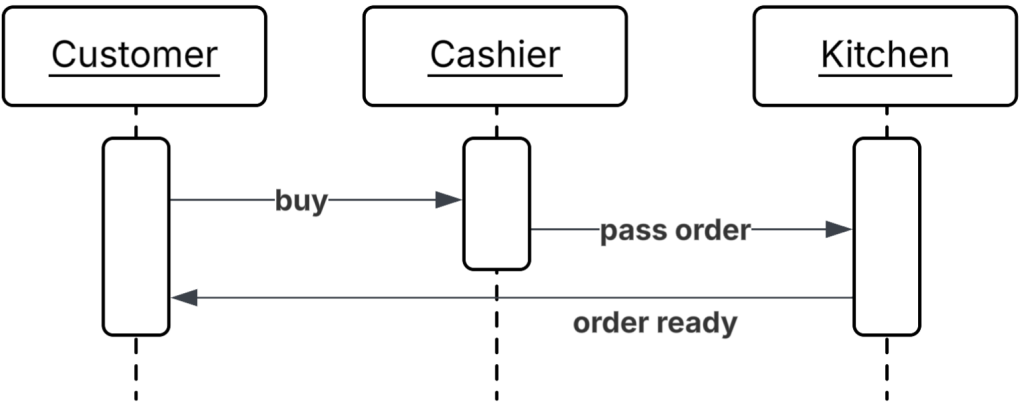
Things get interesting when we add more entities. Consider the example below that represents the data flow for a fast food restaurant. Customers start the flow by telling Cashiers they want to buy something. When the payment is finished, Cashiers pass the order to the Kitchen. When the order is ready, the Kitchen will notify the Customer so they can collect their order.
Sequence diagrams can get as detailed as you want. You may want to include return values, arguments passed in the calls, and even define loops. However, if you or your team are new to UML diagrams, I would strongly advise to start with simple diagrams first and slowly introduce complexity as everyone gets familiar with the concepts.
Final Thoughts
UML is standard notation that allows us to create simple visual representations of complex ideas.
For this very reason, I strongly believe that everyone involved in software development should learn it, not just software engineers, as this allows for improved communication between all members of a software team.
There are lots of tools available to draw UML diagrams, so there’s no excuse to not do it! At the time of writing, Miro and Lucidchart come to mind, but there are many others. If in doubt, ask your teammates or explore the software your company has access to.
Note that UML is not magic though: it’s just a tool. Don’t forget that the most important thing is collaboration with your team, and UML is a great tool that can facilitate those interactions. As the Agile Manifesto says, “we value Individuals and interactions over processes and tools“.
Cheers,
José Miguel
Share if you find this content useful, and Follow me on LinkedIn to be notified of new articles.